1、Common Bending Dies
The common bending dies are shown in the figure below. To extend the life of the dies, rounded corners should be used in part design whenever possible.

For edges with a height that is too small, even with bending dies, it is not conducive to forming. Generally, the bending edge height L should be at least 3 times the thickness (including the wall thickness).
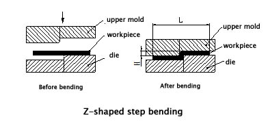
Processing of Steps
For some sheet metal Z-shaped steps with a lower height, manufacturers often use simple dies on stamping presses or hydraulic presses for processing. For small batches, segment difference dies can also be used on bending machines, as shown in the figure below. However, the height H should not be too high, generally it should be within (0–1.0) times the thickness. If the height is between (1.0–4.0) times the thickness, consider using a die with an unloading structure according to the actual situation.
The step height of this die can be adjusted by adding shims, so the height H is arbitrarily adjustable. However, there is a disadvantage: the length L dimension is not easy to ensure, and the verticality of the vertical edge is not easy to guarantee. If the height H is large, consider bending on a bending machine.
Bending Machines
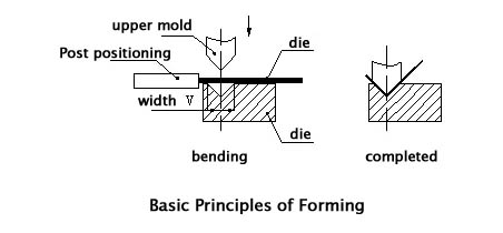
There are two types of bending machines: ordinary and CNC (numerical control). Due to high precision requirements and irregular bending shapes, sheet metal bending for communication equipment generally uses CNC bending machines. The basic principle is to use the bending die (upper die) and V-groove (lower die) of the bending machine to bend and shape the sheet metal parts.
Advantages: Easy clamping, accurate positioning, and fast processing speed.
Disadvantages: Low pressure, only capable of processing simple shapes, and lower efficiency.
Basic Principles of Shaping
The basic principle of shaping is shown in the figure below.
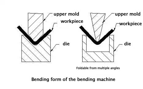
Bending Die (Upper Die)
The form of the bending die is shown in the figure below. During processing, it is mainly selected according to the shape required by the workpiece. Manufacturers usually have a variety of bending die shapes, especially those with a high degree of specialization, who customize many shapes and specifications of bending dies for various complex bends.
The lower die generally uses a V-groove with V=6t (t is the material thickness).
There are many factors that affect bending processing, including the upper die radius, material, thickness, lower die strength, and lower die mouth size. To meet product requirements and ensure the safe use of the bending machine, manufacturers have already standardized the bending die series. We need to have a general understanding of the existing bending dies during the structural design process. See the figure below, the left side is the upper die, and the right side is the lower die.
**Basic Principles of Bending Processing Order**:
- Bend from the inside out.
- Bend from small to large.
- Bend special shapes first, then general shapes.
- The previous process should not affect or interfere with subsequent processes.
The current bending forms are generally shown in the figure below.
2、Bending Radius
When bending sheet metal, there must be a bending radius at the bending point, which should not be too large or too small and should be appropriately selected. A too small bending radius can easily cause cracking at the bend, while a too large bending radius can cause the bend to rebound.
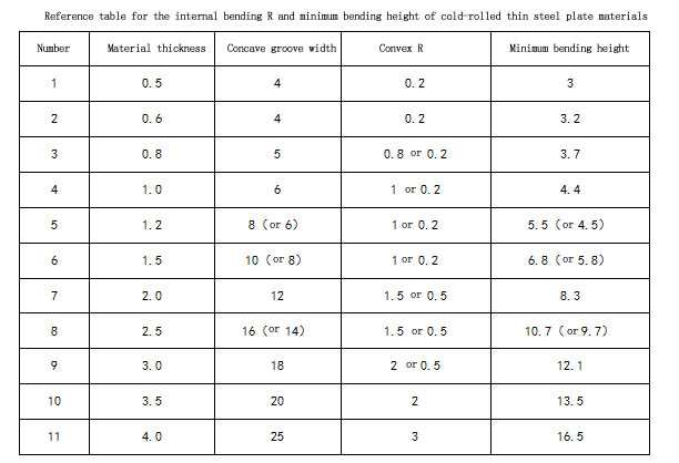
The preferred bending radius (inner radius) for various materials of different thicknesses is shown in the table below.

The data in the table above is preferred and for reference only. In fact, the fillet of the manufacturer’s bending die is usually 0.3, and a few bending dies have a fillet of 0.5.
For ordinary low-carbon steel plates, anti-rust aluminum plates, brass plates, and copper plates, an inner fillet of 0.2 is no problem, but for some high-carbon steel, hard aluminum, and super-hard aluminum, this bending fillet will cause bending fracture or outer fillet cracking.
3、Bending Springback
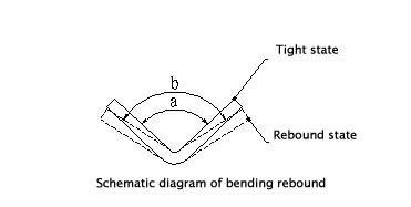
Springback angle Δα = b – a, where b is the actual angle of the workpiece after springback, and a is the die angle.
**Size of the Springback Angle**
The springback angle for a single 90-degree free bending is shown in the table below.

Factors Affecting Springback and Measures to Reduce It
- The mechanical properties of the material: The size of the springback angle is directly proportional to the yield point of the material and inversely proportional to the elastic modulus E. For sheet metal parts with high precision requirements, to reduce springback, materials should be chosen as low carbon steel as much as possible, and high carbon steel and stainless steel should not be chosen.
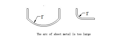
- The relative bending radius r/t: The larger the value, the smaller the degree of deformation, and the larger the springback angle Δα. This is an important concept. The fillet of sheet metal bending should be as small as possible within the allowable range of material performance, which is conducive to improving accuracy. It is especially important to avoid designing large radii, as shown in the figure below, which poses great difficulty for production and quality control.
4、Minimum Bending Edge Calculation for One-time Bending
The starting state of L-shaped bending is shown in the figure below.
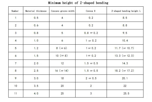
The starting state of Z-shaped bending is shown in the figure below.

The minimum bending dimensions L for Z-shaped bending of sheet metal of different material thicknesses are shown in the table below.
Hi, this is a comment.
To get started with moderating, editing, and deleting comments, please visit the Comments screen in the dashboard.
Commenter avatars come from Gravatar.