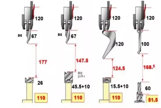
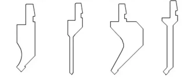
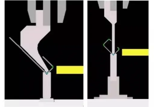
The press brake toolings are divided into two parts.
The toolings installed on the top of the ram are called punches, and the bottom toolings on the workbench are called dies.
The two parts work together on the metal plate to complete the bending of the workpiece.
The process that which the punch of the press brake exerts a force on the metal plate on the die is the bending process.
The upper die presses the metal plate through different power sources driving the ram.
The driving sources include mechanical, hydraulic, and servo motors.
Standards of Press Brake Toolings
There are different types of punches and dies.
The accuracy and efficiency of bending can be improved only by selecting the correct matching punches and dies for bending.
The standard size toolings are more convenient to replace. Because the design of tooling parts with standard dimensions is consistent.
In this way, there is no need to make too many adjustments when replacing the punches and dies. These toolings are kept in the same position to replace conveniently.
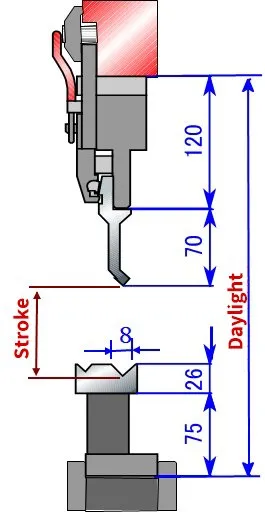
The upper parts of the ram of the press brake need a clamping device for fixing the punches.
The clamping can fix the punches in the required position. The punches bend the metal plate with the motion of the ram.
Die segmentation can facilitate the bending process of various sized workpieces. Press brake toolings require very high accuracy.
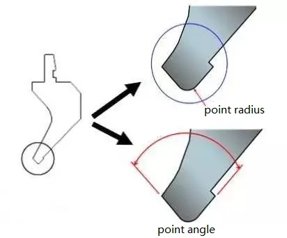
Especially the accuracy of punch tip and die shoulders. Cause these parts will directly contact the sheet metal during bending.
Moreover, the punches and dies with high precision can reduce the adjustment in the installation process.
Types of Punches and Dies
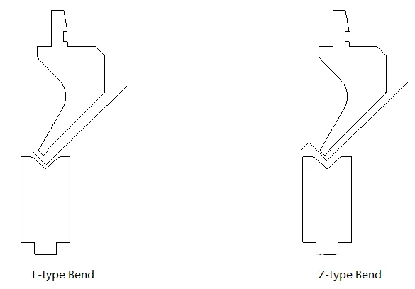
Press brake dies include V-die, U-die, and Z-die, and the most common is V-die. The minimum flange length shall be at least 4 times the material thickness.
Otherwise, the exact bending angle cannot be obtained. V-die sets with different opening widths match the corresponding punches.
In this way, the press brake can bend at different angles and different materials.
Press brake punches are mainly classified into three types: straight punch, gooseneck punch, and acute punch.
The die of the press brake can be divided into single V die, double V dies, and Multi-V die.
Consideration for Tooling Selection
Bending Material
First, the type of metal you want to bend is an important factor.
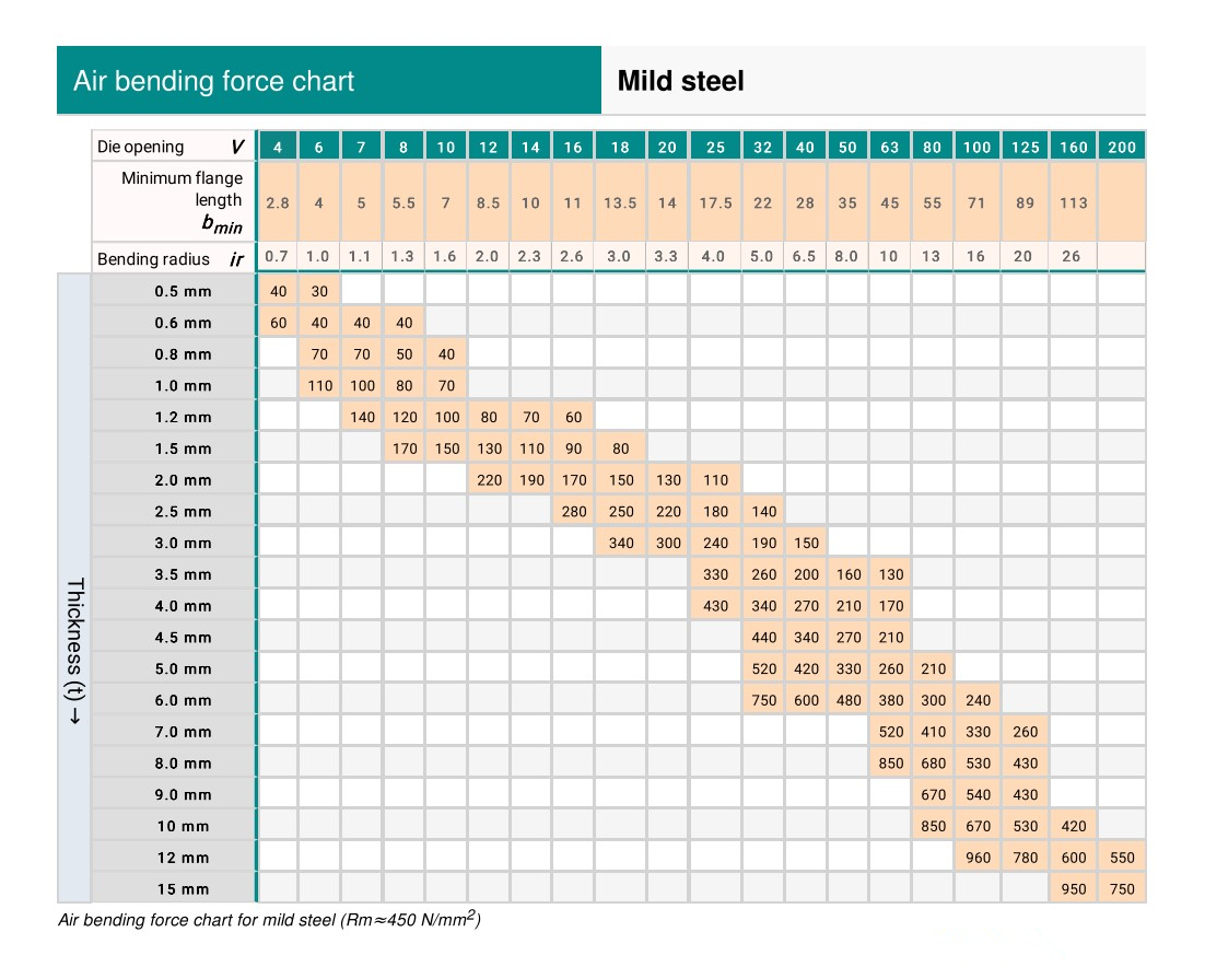
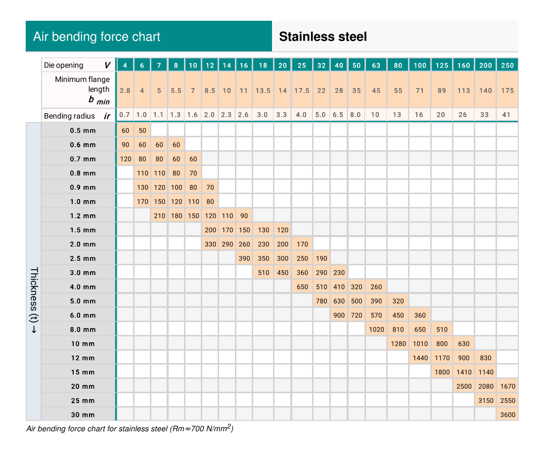
The thickness of the metal determines the die opening, bending radius, and bending angle.
For example, some steels have greater strength and higher resistance than other steels.
This resistance is the tensile strength(UTS) of the metal. The tensile strength of metals is different, which requires different strength molds.
In addition, it needs to be considered that the length of the metal plate determines how many toolings are required.
The V Opening and Radius of Material
When bending sheet metal, if the thickness and metal type are the same, there is not only one V-die opening size.
The sheet metal will not be lost during bending. If the internal radius is less than the thickness of the metal plate, the plate will be stretched, which will lead to the deformation of the workpiece. While a radius greater than the thickness of the sheet will not cause deformation.
When choosing the perfect V-die opening, we should not only avoid radius deformation but also choose a smaller radius.
The rule of 8
There is a rule of thumb applicable to the V-opening of press brake dies: the rule of 8.
The rule of 8 is based on 60000 PSI tensile cold-rolled steel. It stipulates that the V opening die shall be eight times the thickness of the bending material.
The rule of 8 applies to the most bending processes. Within the specified tonnage range, an internal radius approximately equal to the thickness of the material can be produced.
However, this is not a perfect law, because the factor will increase or decrease with the variation of the material thickness.
As a result, the width of some V-die openings is 6 times, 10 times, or even 12 times the thickness of the material.
The thicker plate is usually 10 times. Because thicker plates tend to lose some ductility.
So we use a larger V opening to distribute the force in a larger area and avoid cracks in the plate. Before determining the press brake dies, first determine the thickest and thinnest metal sheet to be bent.
Use the rule of 8 to determine the correct size of the V dies.
Select the smallest V to die and double its size to determine the next V die until the maximum mold is reached. If an exact match cannot be found, the dimensions should be rounded to the nearest available mold.
V opening affects the radius of bending material.
It is ideal on most bending materials when the internal radius equals 1 thickness. If the inner radius is less than 1 thickness, it means that the material extracted from the radius disappears.
In plate bending, if the inner radius is less than 1 thickness, we can see how the “side bulge” appears at the bending.
The larger the V-die opening, the larger the radius of the metal plate.
However, the tensile strength of the material will also affect the radius.
On a given V-die opening, the stronger the material, the greater the radius.
On mild steel, the bending radius (R) is usually 1 / 8 of the V-die opening, resulting in the following formula: R=V/8
This rule will vary for different metal types.
Minimum Length of the Flange or Leg
When selecting V-shape dies, pay attention to the flange length or leg required by the workpiece.
When bending, the sheet metal must always be in direct contact with the shoulder of the die.
Less than the specified flange length will fall into the V-shape opening.
If so, the bending result will be inaccurate.
Therefore, the larger the V-shape opening, the larger the minimum flange or leg on the metal plate.
The minimum flange formed by V-die is about 70% of the opening of the standard V-die.
The acute angle die can reach 110% or more of the V-die opening.
Before determining the minimum flange length, the sheet metal should be placed on the die.
In this way, the material contact on the die shoulder is equal to 20% of the V-die opening.
Correct tooling selection and material use can improve the accuracy of bending workpieces.
They will affect the bending angle, internal radius, minimum flange length, and the appearance of the whole workpiece.
Using the correct tooling can improve bending efficiency, reduce cost, prevent profile deformation, and protect the safety of press brake operators.

